Overview
PASS/Nozzle-FEM is designed for stresses and flexibility calculation of nozzle-to-shell junctions using the Finite Element Method (FEM). The program also calculates nozzle’s allowable loads and estimates strength of the nozzle’s junctions for wide range of geometric configurations and operating conditions. Nozzle-FEM helps to provide higher level of the equipment safety along with reducing labour costs at the design stage. The program is recommended for designing and industrial safety review of oil and gas, refining, petrochemical, chemical, power and other industrial facilities.
Unlike the universal FEM programs (ANSYS, NASTRAN, COSMOS, etc.), this program does not require special training and can be used by any mechanical engineer. Creation of finite element mesh and estimation of calculation results are performed automatically. FEM calculation, as opposed to semi-analytic methods (i.e. WRC 107/297, GOST 34233.3-2007, etc.), expands the program application range and increases analysis accuracy.
The program performs stress analysis for nozzles (including trunnions) of arbitrary geometry connected to cylindrical and conical shells, as well as elliptic, hemispherical and flat heads. Also one performs stress analysis of special cases: bend stanchion, support skirt, rectangular plate. It takes into account vessel boundary restraints and loads on the nozzle from the adjacent pipeline. Both nozzle and shell membrane, bending and total stresses can be calculated. Calculation of the pipe branch connections is also implemented, enabling detailed stress analysis of non-standard tees and pipelines branch connections.
Along with stress and stability analysis the program also performs nozzle-shell junction flexibility calculation, as this flexibility can considerably influence vessel and piping stresses. During stress analysis of pipeline systems nozzle-vessel junctions are often simulated by anchor supports which leads to overestimation of stresses and tensions. In order to automatically create the appropriate non-standard support in the calculation model, the nozzle-shell junction flexibility calculated by Nozzle-FEM can be passed into the PASS/START-PROF piping stress analysis program.
Powerful capabilities
- Allowable stresses calculation according to the rule codes (ASME, EN, JB, GOST etc)
- Stress analysis of nozzle-to-shell junction from the action of external loads, pressure and thermal expansion
- Creating detail report with calculation results and strength conclusions (HTML, RTF)
- Fatigue assessment according to ASME VIII.2 and GOST
- Allowable loads for nozzle\support and unconstrained shell ends
- Stress intensification factors (SIF) calculation
- Flexibility analysis (stiffness, flexibility factors)
- Calculation of nozzle with non-circle cross-section shapes
- Calculation of multiple user load cases
- Calculation with thermal strains
- Calculation with hydrostatic pressure
- Calculation of bend stanchion
- Calculation of support skirt
- Calculation of nozzle junction into rectangular wall
- Calculation of strength and stiffness as per WRC 537/107(297)
- Calculation of hole reinforcement as per GOST 34233.3-2017
- Strength analysis in corrosive hydrogen sulphide medium (GOST)
Integration
PASS/Nozzle-FEM model can be created and transferred from PASS/EQUIP software.
The special variant of PASS/Nozzle-FEM has been developed for tie-ins (tees and fittings) and shell-to-nozzle junction calculation as per WRC and GOST, to be called directly from PASS/START-PROF software. Any Nozzle-FEM results can also be user in the piping system analysis by PASS/START-PROF in manual mode.
Materials database
The material database includes physical and mechanical properties of vessel elements materials according US, European, Chinese and Russian codes.
User Interface
The program has a modern, convenient, easy and friendly graphical user interface (GUI), which includes interactive user tips and user manuals in English and Russian languages.
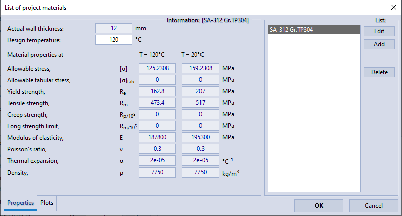
Material choosing.
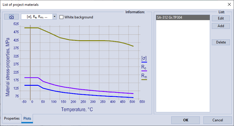
Displaying material properties in graphs.
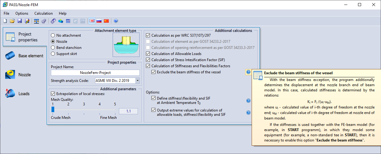
Setting project properties.
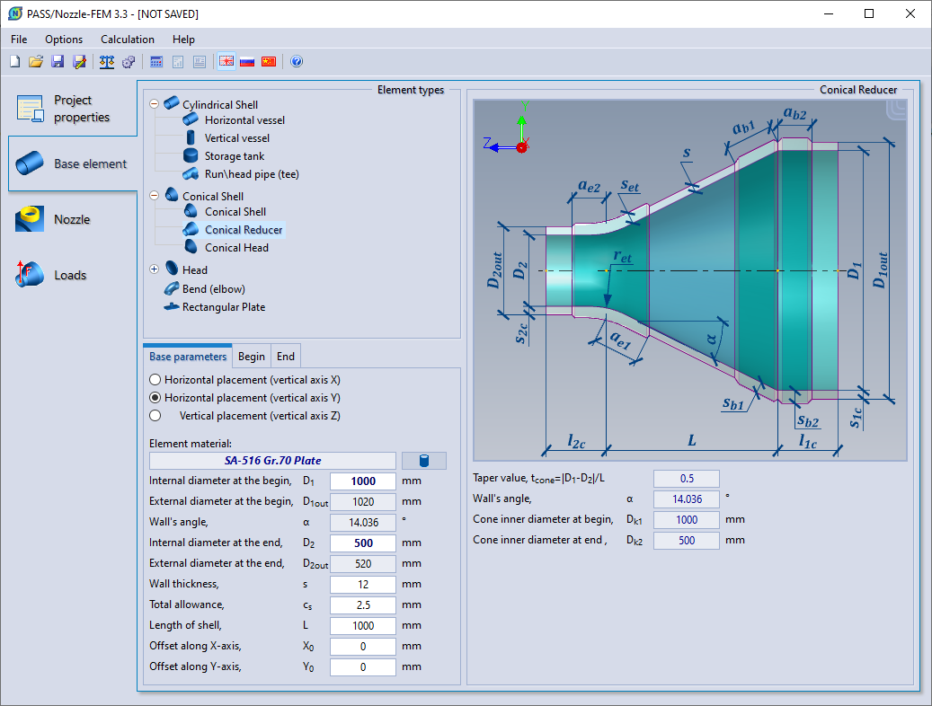
Input of base element data (conical reducer).
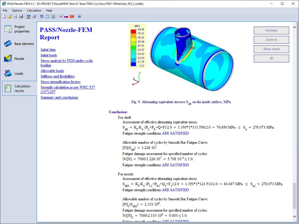
Report of results and strength analysis.
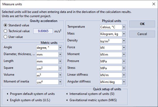
Units setup.
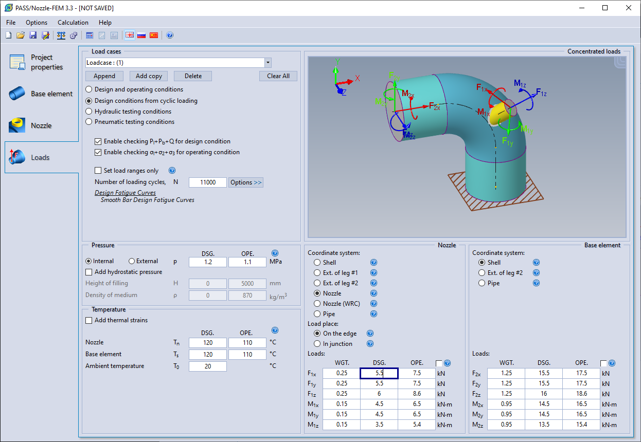
Input of load case data.
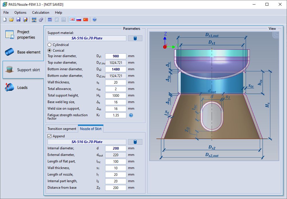
Input of support skirt data.
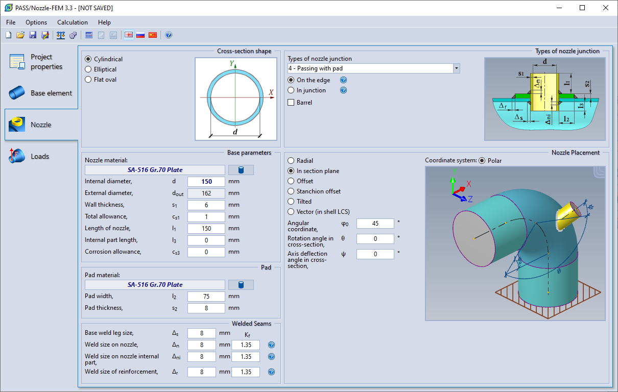
Input of nozzle data.
PASS/Nozzle-FEM allows to create a several base design scheme by attachment element type:
- No attachment
- Nozzle (branch)
- Bend stanchion
- Support skirt
PASS/Nozzle-FEM allows to model a variety shell elements, which greatly simplifies the design model creation:
Cylindrical shell:- Horizontal vessel
- Vertical vessel
- Storage tank
- Runhead pipe (tee)
- Conical shell
- Conical reducer
- Conical head
- Elliptical head
- Hemispherical head
- Torispherical head (dished)
- Flat head
- Conical head
- Bend (elbow)
- Rectangular plate
System Requirements
| Windows 7/8/10+ 64bit | ||
| x86-64 architecture processor | ||
| Depends on Windows version (preferably from 8Gb) | ||
| Video card with OpenGL 2.0+ support and 1GB+ of RAM | ||
| Display resolution at least 800x640, recommended 1366х768 | ||